
the educational site
· networking |
|
· ccna |
|
· bsci |
|
· bcmsn |
|
· bcran |
|
· cit |
|
· links |
|
· courses |
|
· cabling |
· relaxation |
|
· arts |
1-TYPES OF RJ45 2-CONSOLE CABLE 3-DB9 CONNECTORS 4-TERMINAL CONNECTION 5-AUXILIARY PORT new
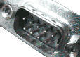
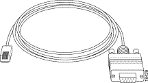
guide 3: DB9 Connectors General Information: 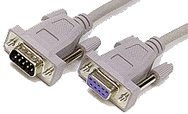 A typical cable using DB9 connectors made by CompuCable.
The DB9 connector is used by serial port devices. On a typical PC
the DB9 connector is located on the back of the computer and is
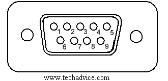
assigned to one of the Com Ports. It has 9 pins arranged in two
rows one on top of the other. The top row has 5 pins and the lower
row has 4 pins.
Pin Signals:
.Pin 1 - Received Line Signal Detect
.Pin 2 - Received Data
.Pin 3 - Transmitted Data
.Pin 4 - Data Terminal Ready (DTR)
.Pin 5 - Signal Ground
.Pin 6 - Data Set Ready (DSR)
.Pin 7 - Request to Send (RTS)
.Pin 8 - Clear to Send (CTS)
.Pin 9 - Ring Indicator (RI)
A typical cable using DB9 connectors made by CompuCable.
The DB9 connector is used by serial port devices. On a typical PC
the DB9 connector is located on the back of the computer and is
assigned to one of the Com Ports. It has 9 pins arranged in two
rows one on top of the other. The top row has 5 pins and the lower
row has 4 pins.
Pin Signals:
.Pin 1 - Received Line Signal Detect
.Pin 2 - Received Data
.Pin 3 - Transmitted Data
.Pin 4 - Data Terminal Ready (DTR)
.Pin 5 - Signal Ground
.Pin 6 - Data Set Ready (DSR)
.Pin 7 - Request to Send (RTS)
.Pin 8 - Clear to Send (CTS)
.Pin 9 - Ring Indicator (RI)
  Serial Interface Modem Cable Pin Definitions:
DB-25 DB-9 Circuit Function Signal Source
Computer/Modem
1 -- AA Chassis Ground Both
2 3 BA Transmitted Data Computer
3 2 BB Received Data Modem
4 7 CA Request to Send Computer
5 8 CB Clear to Send Modem
6 6 CC Data Set Ready Modem
7 5 AB Signal Ground Both
8 1 CF Carrier Detect Modem
12 -- SCF Speed Indicate Modem
20 4 CD Data Terminal Ready Computer
22 9 CE Ring Indicate Modem
Loopback Pinout:
1-7-8
2-3
4-6-9
top
Serial Interface Modem Cable Pin Definitions:
DB-25 DB-9 Circuit Function Signal Source
Computer/Modem
1 -- AA Chassis Ground Both
2 3 BA Transmitted Data Computer
3 2 BB Received Data Modem
4 7 CA Request to Send Computer
5 8 CB Clear to Send Modem
6 6 CC Data Set Ready Modem
7 5 AB Signal Ground Both
8 1 CF Carrier Detect Modem
12 -- SCF Speed Indicate Modem
20 4 CD Data Terminal Ready Computer
22 9 CE Ring Indicate Modem
Loopback Pinout:
1-7-8
2-3
4-6-9
top
guide 4: Console Port Settings for terminal Connection Before you connect a terminal to the console port,configure the terminal to match the router console port as follows: .9600 baud .8 data bits .no parity .2 stop bits (9600 8N2) OR 1 stop bit* *Dependant on the router Types of Console and AUX Connectors: As described in the following table,Cisco routers have three types of console and AUX connectors: .RJ-45 .DB-25 DCE .DB-25 DTE There are three styles of RJ-45-to-DB-25 connectors: DCE style (modem), DTE style, and DCE style (non modem). Each one has a different role. Generally, DTE is for terminals, DCE (modem) is for modems, and DCE (non-modem) is obsolete. Note: You can change a DCE style (non modem) to a DCE style (modem) by moving pin 6 to pin 8. Console and AUX Connectors for Cisco Routers:
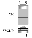
 There are three types of commonly used RJ-45 cabling:
straight, cross and rolled. If you hold the two ends
of an RJ-45 cable side by side, you'll see eight colored
strips, or pins, at each end. If the order of the colored
pins is the same at each end, then the cable is straight.
If the order of the colors is reversed at each end, then
the cable is rolled.
Adapters:
There are two types of adapters needed to connect a PC to a router.
.RJ-45-to-DB-9 Adapter
.RJ-45-to-DB-25 Adapter
RJ-45-to-DB-9 Adapter:
This adapter connects a router to a PC though a COM port.
There are three types of commonly used RJ-45 cabling:
straight, cross and rolled. If you hold the two ends
of an RJ-45 cable side by side, you'll see eight colored
strips, or pins, at each end. If the order of the colored
pins is the same at each end, then the cable is straight.
If the order of the colors is reversed at each end, then
the cable is rolled.
Adapters:
There are two types of adapters needed to connect a PC to a router.
.RJ-45-to-DB-9 Adapter
.RJ-45-to-DB-25 Adapter
RJ-45-to-DB-9 Adapter:
This adapter connects a router to a PC though a COM port.
guide 5: Auxiliary Port Signals and Pinouts Use the thin, flat, RJ-45-to-RJ-45 roll-over cable and RJ-45-to-DB-25 male DCE adapter (labeled "MODEM") to connect the auxiliary port to a modem. the figure below shows how to connect the auxiliary port to a modem. the table lists the pinouts for the asynchronous serial auxiliary port, the RJ-45-to-RJ-45 roll-over cable, and the RJ-45-to-DB-25 male DCE adapter (labeled "MODEM"). Connecting the Auxiliary Port to a Modem : 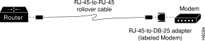 Auxiliary Port Signaling and Cabling Using a DB-25 Adapter
plus de guides sont a venir, alors revenez souvent....merci contactez-moi ici |
||||||||||||||||||||||||||||||||||||||||||||||||||||||||||||||||||||||||||||||||||||||||||||||||||||||||||||||||||||||||||||||||||||||||||||||||||||||
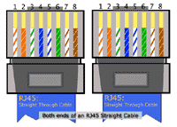 RJ-45 Straight-through (Ethernet) Cable Pin-outs
Signal Pin Pin Signal
Tx+ 1 1 Tx+
Tx- 2 2 Tx-
Rx+ 3 3 Rx+
- 4 4 -
- 5 5 -
Rx- 6 6 Rx-
- 7 7 -
- 8 8 -
2-Crossover Cable:
In a crossover cable, the first (far left) colored wire at one end
of the cable is the third colored wire at the other end of the cable.
RJ-45 Straight-through (Ethernet) Cable Pin-outs
Signal Pin Pin Signal
Tx+ 1 1 Tx+
Tx- 2 2 Tx-
Rx+ 3 3 Rx+
- 4 4 -
- 5 5 -
Rx- 6 6 Rx-
- 7 7 -
- 8 8 -
2-Crossover Cable:
In a crossover cable, the first (far left) colored wire at one end
of the cable is the third colored wire at the other end of the cable.
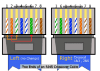 RJ-45 Crossover (Ethernet) Cable Pin-outs
Signal Pin Pin Signal
Tx+ 1 3 Rx+
Tx- 2 6 Rx-
Rx+ 3 1 Tx+
- 4 4 -
- 5 5 -
Rx- 6 2 Tx-
- 7 7 -
- 8 8 -
3-Rolled Cable:
In a rolled cable, the colored wires at one end of the cable
are in the reverse sequence of the colored wires at the other end
of the cable.
RJ-45 Crossover (Ethernet) Cable Pin-outs
Signal Pin Pin Signal
Tx+ 1 3 Rx+
Tx- 2 6 Rx-
Rx+ 3 1 Tx+
- 4 4 -
- 5 5 -
Rx- 6 2 Tx-
- 7 7 -
- 8 8 -
3-Rolled Cable:
In a rolled cable, the colored wires at one end of the cable
are in the reverse sequence of the colored wires at the other end
of the cable.
 RJ-45 Rolled (Console) Cable Pin-outs
Signal Pin Pin Signal
- 1 8 -
- 2 7 -
- 3 6 -
- 4 5 -
- 5 4 -
- 6 3 -
- 7 2 -
- 8 1 -
Note: CAB-OCTAL-ASYNC, the 8-port RJ-45 adapter that is used with the
Cisco 2509, 2510, 2511, and 2512, is the same as a rolled cable.
RJ-45 to DB-9 Female*
RJ-45 Rolled (Console) Cable Pin-outs
Signal Pin Pin Signal
- 1 8 -
- 2 7 -
- 3 6 -
- 4 5 -
- 5 4 -
- 6 3 -
- 7 2 -
- 8 1 -
Note: CAB-OCTAL-ASYNC, the 8-port RJ-45 adapter that is used with the
Cisco 2509, 2510, 2511, and 2512, is the same as a rolled cable.
RJ-45 to DB-9 Female*
 This cable is also known as Management Cable.*Cisco is providing
this cable with its 600, 800, 1600 and 1700 series routers.
This cable is also known as Management Cable.*Cisco is providing
this cable with its 600, 800, 1600 and 1700 series routers.
 (To the Computer).
 (To the Cisco router)
9 PIN D-SUB FEMALE to the Computer
(To the Cisco router)
9 PIN D-SUB FEMALE to the Computer
copyright ©2002 chahada.Created and managed with chahada.All rights reserved .webmaster : DJAMEL GUESSOUM .BARIKA -ALGERIE-